QUAD TECH:
The QUAD TECH page will provide photos of basic QUAD COPTER/Multi- Motors Copters introductory technology below. Staring with the FLIGHT CONTROLER, which there are many different devices used in the Multi- Motors Copters operations. And the main function of the FLIGHT CONTROLERS, will ensure all motors with propellers of your Multi- Motors Copters design are spinning in a clock wise and counter clock wise synchronized manner. While the synchronized motors are spinning a command can be sent to the FLIGHT CONTROLER that is plunged into a receiver, that's binding to the frequency of your transmitter. And these commands will cause some if not all those synchronized spinning motors to increase or decrease in speed, resulted in the production of Yaw, Pitch and Roll with the end results being directional flight control. Bottom line, the FLIGHT CONTROLERS will ensure, that you are in control of the directional flight of your Multi- Motors Copter and all it's motors.
Also. it's very important to place and position the FLIGHT CONTROLER in the center of your Multi- Motors Copter design in order to achieve the most possible stable flight!
IMPORTANT NOTICE:
Always remember to remove all propellers from your Multi- Motors Copter before working on it, expressly if you are setting the proper clock wise or counter clock wise rotation spinning direction of each motors. Also, remember, to always turn on the TRANSMITTERS / Radio first, before switching the power of you model aircraft on,
Furthermore.please be mindful of the LAWS surrounding the overall operation of MULTI-MOTOR COPTERS or to most DRONE, And click on the links as follow to learn a little more about the DRONE LAWS: (AMA Response to FAA Registration Mandate of Hobby Drones & RC Aircraft) www.youtube.com/watch?v=bj9isLNQLPY or (The FAA's Mandatory Drone Registration Rules are Illegal Say Two Drone Attorneys) www.youtube.com/watch?v=I6bZA8NiAlU or drone registration 2015 enforceable? reasonable? https://www.youtube.com/watch?v=SmrTFRvrolI


Above is called a FLIGHT CONTROLER, and essential for Multi- Motors Copters. To the far right shows, a photo of a RECEIVER, and where you plug the FLIGHT CONTROLR into.


TRANSMITTERS to the left: Note; a 4Channel radio system is required for- Multi-Motors Copters." Two different RECEIVERS is shown in the middle shown above, followed by three different types of motors to the right.


Two different Propellers design, and Four 6x4.5 , 1 or 3-blade Clockwise (CW) and Counter Clockwise (CCW )size propellers will be used in this Multi-Motors Copters build. In the middle are Electronic Speed Controllers/ESCs. And on the right are three Power Supplies/ Batteries


Diagram of Multi-Motors Copters propeller set up show above. Distribution Board for ESCs and Motors installation show in the middle. Full set up of primary equipment above.
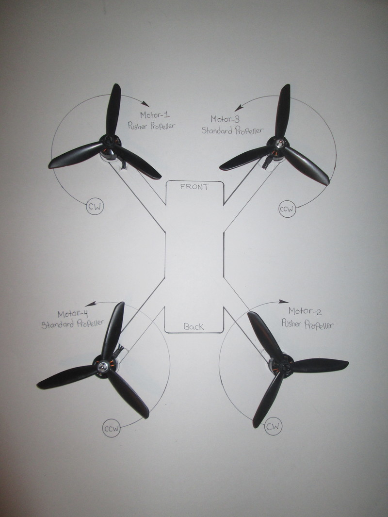
The above diagram is very important: because it shows the proper spin direction of each motors of your quad copter, to ensure you achieve flight. Before, going on any further please note, (CW) means Clockwise and (CCW) means Counter Clockwise. Also, pay close attention to the propeller set up, which is very important as well! And the set up should be as followed: Start by identifying each motor, by number, shown in the diagram above. Now, be mindful, of the two different types of propellers, one being a Standard and the other being a Pusher Prop, because it has reverse pitch, I respectfully suggest that you learn more about Propeller Technology to understand Propeller pitch.
Now, moving on, to focus on motor -1 set-up to spin Clockwise with a Standard Propeller follow by motor -2 set-up to spin Clockwise with a Standard Propeller as shown in the above diagram. However, Motor -3 and 4 are set up to spin Counter Clockwise with Pusher props as shown in the above diagram. Also, On the most part, the process to ensure motors are spinning correctly is a simple process. And that process is the switching of two wires of the three wires of the brushless motor wires plunged into the ESCs or the switching of the two wires of the brushed motor two wires plunged into the ESCs.
Now, moving on, to focus on motor -1 set-up to spin Clockwise with a Standard Propeller follow by motor -2 set-up to spin Clockwise with a Standard Propeller as shown in the above diagram. However, Motor -3 and 4 are set up to spin Counter Clockwise with Pusher props as shown in the above diagram. Also, On the most part, the process to ensure motors are spinning correctly is a simple process. And that process is the switching of two wires of the three wires of the brushless motor wires plunged into the ESCs or the switching of the two wires of the brushed motor two wires plunged into the ESCs.
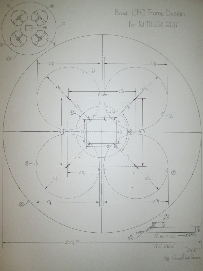
The above UFO frame diagram have measurements to aid any first time builders, that wants to start with a simple custom UFO frame build. And to simplify the drawing diagram above, would be to identify all important measures by letter A-H. Starting with (A) which is an extension part if you are cutting from a sheet of Styrofoam material with a 1/2 in thickness or you can cut from a sheet o Styrofoam material with a thickness of 1"in. (B) shows the center of the UFO frame design with a with it's 3'x 2 3/8 rectangular cutout, for the purpose of having the overall UFO frame design placed onto the "SHAFT BRACKET" product from the UFO STORE. (C), (D), (E) and (F) are partially 6 3/16 in circular cutouts, for motors and propellers installation. (G) shows the overall UFO frame design above with a diameter of 20 2/8 in. (H) shows a complete illustration top view, of the UFO custom frame design with propellers in the upper left corner of the drawing diagram above.
ATTENTION: before using the above drawing diagram, please, beware of the possible measurements inaccuracies largely due, to the many design charges. And, with that said, THE UFO STORE online personnel, strongly advised you to design and build your first custom UFO design frame, from your imagination. And I hope, in the name of creativity, that some of your custom UFO design will not be the traditional disk shaped craft design.
ATTENTION: before using the above drawing diagram, please, beware of the possible measurements inaccuracies largely due, to the many design charges. And, with that said, THE UFO STORE online personnel, strongly advised you to design and build your first custom UFO design frame, from your imagination. And I hope, in the name of creativity, that some of your custom UFO design will not be the traditional disk shaped craft design.


All final cut UFO frame design shown on the left. And shown in the middle, is a scroll saw used to make all cuts to fabricate the UFO design frame. And, shown on the right is a completed UFO frame, which is outfitted with the HARNESS BRACKET-x1 and the JJRC Quad Copter, and now, ready to fly. Also, there is a possible benefit when housing your model air frame with motors and electronics, into your custom UFO designed frame,that may serve as a means of a protection shield of motors and electronics during an unfortunate crash.
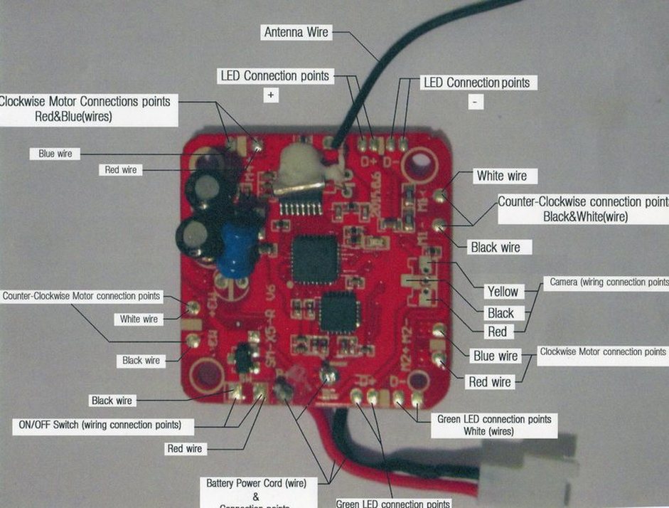
The above Photo Diagram is a Flight Control board for Micro Quad operators to used for wiring reference.


The first photo above shows where to plug the wire into the FLIGHT CONTROLER'S two slots marked A.E.R. and the other slots marked THR. And the second photo above shows the wire plugged into the slots marked with numbers such as CH1-CH-4 as shown of the RECEIVER from the FLIGHT CONTROLER. And the third photo above, shows the wires from the FLIGHT CONTROLER plugged into a RECEIVER that has its plug in slots marked with word abbreviation such as AUX 1, GEAR,,RUDD,ELEV,THRO and BND/DAT as show in the first photo above.


The first photo above shows the FLIGHT CONTROLER and RECEIVER are wired together. And, the second photo shows the four switch set-up on the upper right side of the FLIGHT CONTROLER , and the purpose for these switches, would be to set your multi-motor copter flight configuration. And, the third photo shows where the ESCs from the motors are plugged into the slots of the FLIGHT CONTROLER marked M1-M6.
